tpw-saksham
Technical Product Comparison
| Number of channels |
08 Channels |
16 Channels |
16 Channels |
16 Channels |
| Type Of Analog Output |
0/4-20 mA |
0/4-20 mA |
0/4-20mA |
0/4-20 mA |
| Hardware Functional Status |
From July 22 |
From July 22 |
1.00.001 |
From July 22 |
| Firmware Version |
1.00.001 |
| Firmware Update Possible |
Yes |
| Engineering Software |
CODESYS V3.5 SP19 and above |
| Mounting |
Base Unit TBUS-PPPPPPPP |
| Galvanic Isolation |
Yes |
| Galvanic Isolation Group |
08 Group |
16 Group |
— |
— |
| Channels In One Group |
1 Channel |
1 Channel |
1 Channel |
16 |
| Output Short-Circuit Protection |
Yes, For each Channel (For mA Channel only) |
Yes, For each Channel (For mA Channel only) |
Yes, For each Channel |
— |
| Output Over current Protection |
Yes (40 mA) |
Yes (40 mA) |
Yes (40 mA) |
— |
| Galvanic Isolation Groups |
— |
— |
16 |
1 |
| Input Short-Circuit Protection |
— |
— |
— |
Yes, For Each Channel (For mA Channel only) |
| Input Over-Current Protection |
— |
— |
— |
Yes (40 mA) |
| Power Supply From |
Top Side De-Coded Plug-In Screw Terminal |
| Normal Supply Voltage |
24 V DC |
| Low Supply Voltage |
21.6 V DC |
| High Supply Voltage |
26.5 |
| Reverse Polarity Protection |
Yes |
| Maximum Current |
190 mA |
350 mA |
— |
— |
| Current Per Channel Permissible |
21.5 mA |
21.5 mA |
25 mA |
— |
| Power Loss |
less than 1 W |
| Load Resistance |
370 Ω, Max |
| Input Current |
— |
— |
0.5 A |
0.5 A |
| Input Current Per Channel (Permissible) |
— |
— |
— |
25 mA |
| Transmitter Power |
— |
— |
— |
Yes |
| Output Range |
4-20 mA |
| Range |
Scalable |
Scalable |
0-20 mA |
Scalable |
| Resistive Load |
0.5 ms |
| Capacitive Load |
1 ms |
| Inductive Load |
1 ms |
| Two Wire Connection, Curent O/P |
Yes |
| Parameterization in Run |
Yes |
| Calibration in Run |
Yes |
| Automatic Encoding |
No |
| Mechanical Coding Element |
Yes |
| Linearity Error |
0.1% ( Input Range) |
0.1% (Input Range) |
— |
0.1% (Input Range) |
| Operational Error |
0.5% (Input Range) |
| Basic Error |
0.3% (Input Range) |
| Substitute Value Can Applied |
Yes |
| Crosstalk Between Outputs |
-50dB |
-50dB |
-50 dB |
-50 dB |
| Yes |
— |
— |
0.1% (Input Range) |
— |
| Diagnostic Alarm |
Yes |
| Limit Alarm |
Yes |
| Function Of Diagnostic |
Available |
| Diagnostic Alarm |
Yes |
| Module Fuse Blown Indication |
Yes |
| Wire-Break |
No |
| Short-Circuit |
No |
No |
No |
— |
| Channel Diagnostic |
No |
No |
— |
— |
| Channel Diagnostics |
— |
— |
No |
No |
| Short Circuit |
— |
— |
— |
No |
| Power Of Indication |
Yes |
| Channel Status |
No |
| Channel Diagnostics (Wire Break Joint) |
No |
No |
— |
— |
| Module Diagnostics (Back-Plane Comm) |
Yes |
| Channel Diagnostics (Wire-Break) |
— |
— |
No |
No |
| Separation Between Channels |
Yes (Group Isolation) |
— |
Yes (Group Isolation) |
Yes (Groups Isolation) |
| Separation Between Backplane |
Yes |
— |
Yes |
— |
| Separation Between Channel And System Power Supply |
Yes |
— |
Yes |
Yes |
| Insulation Tested With |
500 VDC |
500 VDC |
370 V DC |
370 V DC |
| Separation Between Channel |
— |
Yes (Group Isolation) |
— |
— |
| Seperation Between Backplane |
— |
Yes |
— |
— |
| Seperation Between Channel And System Power Supply |
— |
Yes |
— |
— |
| Separation Between Backplanes |
— |
— |
— |
Yes |
| Horizontal Installation |
60°C |
| Vertical Installation |
60°C |
| Field Connection |
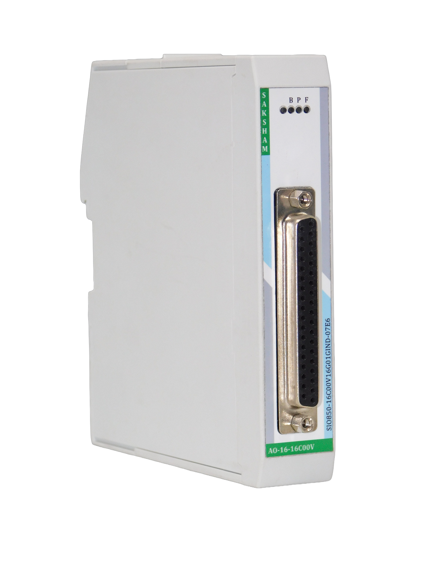
37-Pin D-Sub Female Connector |
| Power Connection |
5 Pin Phoenix Plug-In Screw Connector (De-Coded) |
| Cable Length Max. |
500 m, 1.0 mm² shielded cable |
| Address Space Per Module |
32 Bytes |
| Dimensions (W x H x D) |
25 x 122 x 115 mm |
| Weight |
100g Approx |
| Conformal Coating |
G1, G2 and G3 |
G1, G2 and G3 |
— |
— |