Item No. AIS830-12C04CV04G04GIND
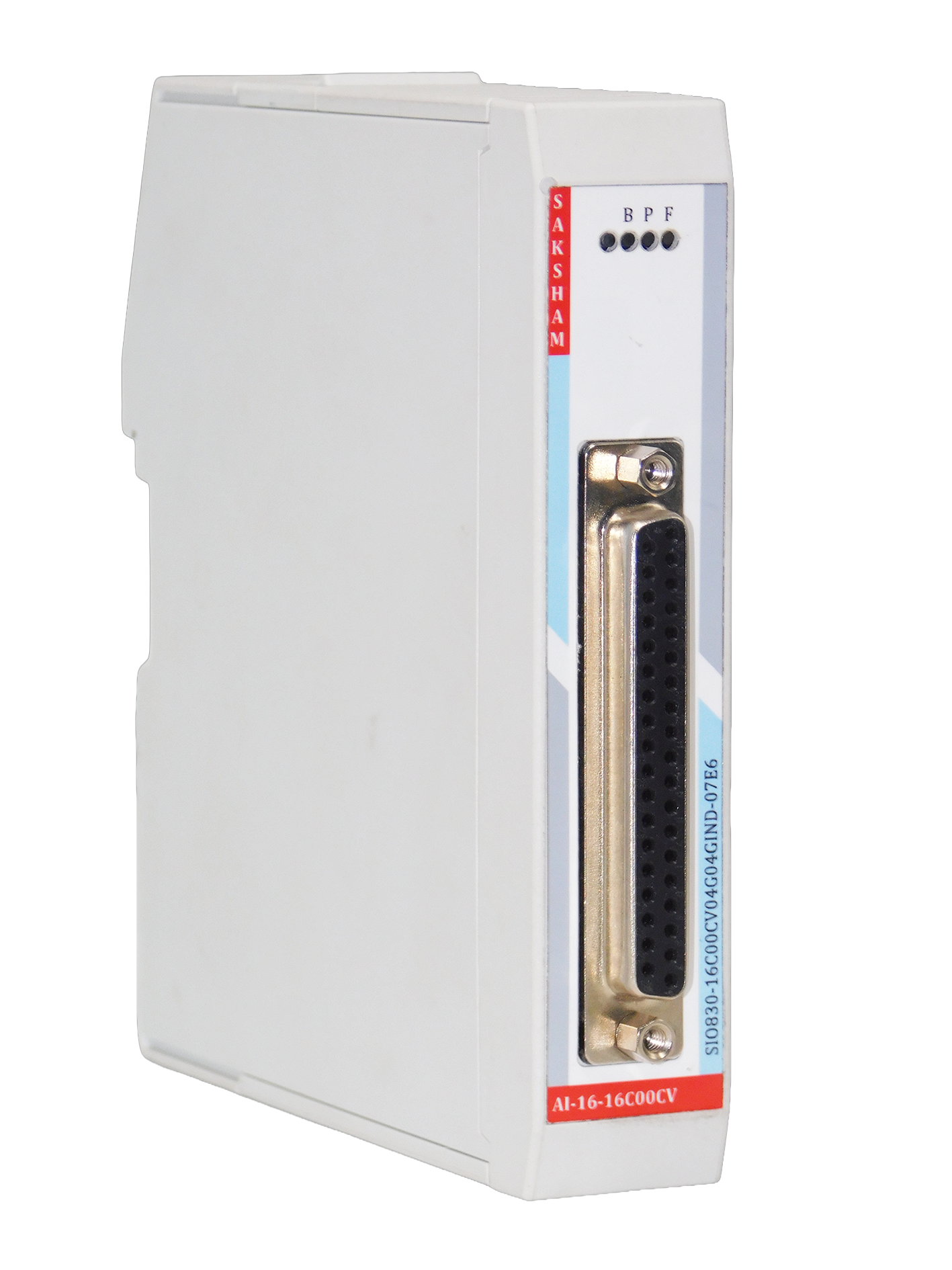
16 Channel Analog Input Module
General Information
| No. of Analog Inputs | 16 Channels |
| Type Of Analog Inputs | 12 Nos 0/4-20 mA 4 Nos. mA/Voltage Selectable |
| Hardware Functional Status | From July 22 |
| Firmware Version | 1.00.001 |
| Firmware Update Possible | Yes |
| Engineering Software | CODESYS V3.5 SP19 and above |
| Mounting | Base Unit TBUS-PPPPPPPP |
Isolation and Protection
| Galvanic Isolation | Yes |
| Galvanic Isolation Groups | 04 Group |
| Channel In One Group | 04 Channel/Group |
| Input Short-Circuit Protection | Yes, For Each Channel (For mA Channel only) |
| Input Over-Current Protection | Yes (40 mA) |
Power Supply
| Power Supply From | Top Side De-Coded Plug-In Screw Terminal |
| Normal Supply Voltage | 24 V DC |
| Low Supply Voltage | 21.6 V DC |
| High Supply Voltage | 26.5 |
| Reverse Polarity Protection | Yes |
| Input Current | 0.5 A |
| Input Current Per Channel Permissible | 25 mA |
| Transmitter Powe | Yes |
| Power Loss | Less than 1 W |
Range
| Input Range | 0-20 mA |
| Input Range | 4-20 mA |
| Input Range | 0-10 V |
| Input Range | 1-10 V |
| Input Range | 0-10 mA |
| Measuring Range | Scalable |
| Input Resistance | 120 Ω in mA selection |
| Input Impedance | 10k ohm in Voltage Selection |
Configuration In Running
| Parameterization in Run | Yes |
| Calibration in Run | Yes |
Hardware Configuration
| Automatic Encoding | No |
| Mechanical Coding Element | Yes |
Conversion Principle
| Analog Input Measuring Principle | Sigma Delta (Integrating) |
Integration And Conversion Time Per Channel
| Resolution (with over-range) | 12 Bit |
| Conversion Time Per Chennal | 100 ms |
Error
| Linearity Error | 0.1% (Input Range) |
| Operational Error | 0.5% (Input Range) |
| Basic Error | 0.3% (Input Range) |
Interference Voltage Separation
| Series Mode Interference | Min 70 dB |
| Common Mode Voltage | Max 10 V |
| Common Mode Interference | 90 dB |
Alarm
| Diagnostics Alarm | Yes |
| Limit Alarm | Yes |
Diagnostic
| Function Of Diagnostic | Available |
| Module Fuse Blown Indication | Yes |
Diagnostic Messages
| Wire-Break | Yes (4-20 mA) |
| Short Circuit | Yes (For mA Channel Only) |
| Channel Diagnostics | Yes |
LED
| Power Indication | Yes |
| Channel Status | No |
| Channel Diagnostics (Wire-Break Joint) | No |
| Module Diagnostics (Back-Plane Comm) | Yes |
Potential Separation
| Separation Between Channels | Yes (Group Isolation) In Group of 4 channel |
| Separation Between Backplane | Yes |
| Separation Between Channel and System Power Supply | Yes |
| Insulation Tested With | 500 V DC |
Ambient Condition
| Horizontal Installation | 0°C |
| Horizontal Installation | 60°C |
| Vertical Installation | 0°C |
| Vertical Installation | 60°C |
Connection
| Field Connection | 37-Pin D-Sub Female Connector |
| Power Connection | 5 Pin Phoenix Plug-In Screw Connector (De-Coded) |
Other Information
| Cable Length Max. | 500 m, 1.0 mm² shielded cable |
| Address Space Per Module | 32 Bytes |
| Dimensions (W x H x D) | 25 x 122 x 115 mm |
| Weight | 160g Approx |
The analog input module is an essential component of our PLC system, designed to seamlessly integrate analog signals into automation processes. It interfaces with various external devices such as sensors, transmitters, variable frequency drives (VFDs), and transducers allowing precise monitoring and control of critical operations within the plant. This model offers 16 channels and incorporates galvanic isolation across four groups of four channels each, ensuring reliable performance and enhanced safety across all connected systems.