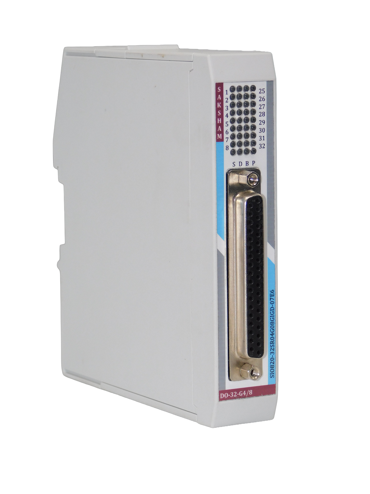
Item No. S820-32SR04G08GINDCC
32 Channel Digital Output Module
General Information
| No. of Digital Outputs | 32 Channels |
| Hardware Functional Status | From July 22 |
| Firmware Version | 1.00.001 |
| Firmware Update Possible | Yes |
| Engineering Software | CODESYS V3.5 SP19 and above |
| Mounting | Base Unit TBUS-PPPPPPPP |
Isolation
| Galvanic Isolation | Yes |
| Galvanic Isolation Groups | 4 |
| Channels in Group | 8 |
Made Of Operation
| DO | Yes |
| DO With Energy Saving Function | No |
| PWM | No |
Power Supply
| Power Supply From | Top Side De-Coded Plug-In Screw Terminal |
| Normal Supply Voltage | 24 V DC |
| Low Supply Voltage | 21.6 V DC |
| High Supply Voltage | 26.5 |
| Reverse Polarity Protection | Yes |
| Maximum Current | 100 mA (Field Current not Included) |
| Power Loss | 0.75 W |
Hardware Configuration
| Automatic Encoding | No |
| Mechanical Coding Element | Yes |
Digital Output
| Number Of Digital Inputs | 32 Channel |
| Type Of Digital Output | Source Output |
| Current Sinking | No |
| Current Sourcing | Yes |
| Digital Output Parameterizable | Yes |
| Short Circuit Protection | Yes |
| Response Threads hold | 1 A |
| Open Circuit Detection | Yes |
| Controlling a Digital Output | Yes |
| Switching Capacity to Resistive Load | 0.5 A |
| Switching Capacity to Inductive Load | 5 W |
Output Current
| For "1" Signal | 0.5 A |
| For "1" Signal | 0.1 mA |
Delay In Output With Resistive Load
| From 0 To 1 | Max 50 µs |
| From 1 To 0 | Max 100 µs |
Parallel Switching Of Two Outputs
| Uprating | No |
| Redundant Control of Load | Yes (using suitable FTA) |
Switching Frequency
| Resistive Load | 100 Hz |
| Inductive Load | 2 Hz |
| Lamp Load | 10 Hz |
Total Current
| Per Channel | 0.5 A |
| Per Module | 16 A |
Module Current as Horizontal Installation
| 30 Degree Celsius | 16 A |
| 40 Degree Celsius | 14 A |
| 50 Degree Celsius | 12 A |
| 60 Degree Celsius | 8 A |
Module Current as vertical Installation
| 30 Degree Celsius | 16 A |
| 40 Degree Celsius | 12 A |
| 50 Degree Celsius | 8 A |
Diagnostic
| Function Of Diagnostic | Yes |
| Diagnostic Alarm | Available |
| Module Fuse Blown Indication | Yes |
Diagnostic Messages
| Diagnostic Info Readable | Yes |
| Supply Voltage Monitoring | Yes |
| Group Error | Yes |
LED
| Power Of Indication | Yes |
| Channel Status | Yes |
| Channel Diagnostics | No |
| Module Diagnostics | Yes |
Potential Separation
| Separation Between Channel | Yes, In Group of 8 Channel |
| Separation Between Backplane | Yes |
| Separation Between Channel And System Power Supply | Yes |
| Insulation Tested With | 500 VDC |
Ambient Condition
| Horizontal Installation | 0°C |
| Horizontal Installation | 60°C |
| Vertical Installation | 0°C |
| Vertical Installation | 60°C |
Connection
| Field Connection | 37-Pin D-Sub Female Connector |
| Power Connection | 5 Pin Phoenix Plug-In Screw Connector (De-Coded) |
Other Information
| Cable Length Max. | 500 m |
| Address Space Per Module | 2 Bytes |
| Dimensions (W x H x D) | 25 x 122 x 115 mm |
| Weight | 140g Approx |
Environmental Protection
| Conformal Coating | G1, G2 And G3 |
The digital output module is a key player in any PLC system, turning digital input commands into important digital output signals. These outputs play a vital role in managing actuators, motors, lights, alarms, and other devices that need external control, all driven by clever logic sequences stored in the PLC’s memory. By selecting the right digital output module, you can ensure top-notch performance and accuracy, along with great stability and safety for all your industrial automation projects. Its all about making your work easier and more efficient.