tpw-saksham
Technical Product Comparison
| Number of channels |
16 Channels |
08 Channels |
08 Channels |
08 Channels |
08 Channels |
| Type Of Analog Input |
0-20 mA |
— |
07 Channels 0-20 mA 01 Channels 0-20 mA Or 0-10 V DC Selectable |
06 Channels 4-20 mA 02 Channels 4-20 mA Or 0-10 V DC Selectable |
0-20 mA |
| Hardware Functional Status |
From July 22 |
| Firmware Version |
1.00.001 |
| Firmware Update Possible |
Yes |
| Engineering Software |
CODESYS V3.5 SP19 and above |
| Mounting |
Base Unit TBUS-PPPPPPPP |
| Type Of Analog Inputs |
— |
0-20 mA |
— |
— |
— |
| Galvanic Isolation |
Yes |
| Galvanic Isolation Group |
4 |
01 |
2 |
— |
02 |
| Channel In Group |
4 |
— |
— |
— |
— |
| Channels In Group |
— |
08 |
4 |
4 |
04 |
| Galvanic Isolation Groups |
— |
— |
— |
2 |
— |
| Power Supply From |
Top Side De-Coded Plug-In Screw Terminal |
| Normal Supply Voltage |
24 V DC |
| Low Supply Voltage |
18.5 V DC |
| High Supply Voltage |
28.5 |
| Reverse Polarity Protection |
Yes |
| Input Current |
0.4 A |
| Input Current Per Channel Permissible |
21.5 mA |
— |
— |
— |
— |
| Transmitter Power |
Yes |
| Power Loss |
Less than 1 W |
| Input Current Per Channels Permissible |
— |
21.5 mA |
21.5 mA |
21.5 mA |
21.5 mA |
| Input Range |
0-10 V DC |
4-20 mA |
0-10 V DC |
0-10 V DC |
4-20 mA |
| Measuring Range |
Scalable |
| Input Resistance |
120 Ω in mA selection |
120 Ω in mA selection |
120 Ω in mA selection |
120 Ω in mA selection |
120 Ω |
| Parameterization In Run |
Yes |
| Calibration In Run |
Yes |
| Automatic Encoding |
No |
| Mechanical Coding Element |
Yes |
| Analog Input Measuring Principal |
Sigma Delta Integrating |
Sigma Delta Integrating |
Sigma Delta Integrating |
Sigma Delta (Integrating) |
Sigma Delta Integrating |
| Resolution With Over Range Max |
12 Bit |
— |
— |
12 Bit |
— |
| Conversion Time Per Channel |
100 ms |
— |
100 ms |
100 ms |
100 ms |
| Resolution (with over-range) |
— |
— |
12 Bit |
— |
12 Bit |
| Linearity Error |
0.1% (Input Range) |
| Operational Error |
0.5% (Input Range) |
| Basic Error |
0.3% (Input Range) |
0.3% (Input Range) |
— |
0.3% (Input Range) |
0.3% (Input Range) |
| Basic Errer |
— |
— |
0.3% (Input Range) |
— |
— |
| Series Mode Interference |
Min 70 dB |
| Common Mode Voltage |
Max 10 V |
| Common Mode Interference |
90 dB |
| For “1” Signal |
Yes |
Yes |
— |
— |
— |
| Function Of Diagnostic |
Available |
| Wire-Break |
Yes (4-20mA) |
Yes (4-20 mA) |
Yes (4-20 mA) |
Yes (4-20mA) |
Yes (4-20 mA) |
| Short Circuit |
Yes |
— |
Yes |
Yes |
Yes |
| Channel Diagnostic |
Yes |
— |
— |
— |
— |
| Short-Circuit |
— |
Yes |
— |
— |
— |
| Channels Diagnostic |
— |
Yes |
Yes |
Yes |
Yes |
| Power Of Indication |
Yes |
| Channel Status |
No |
— |
— |
— |
— |
| Channel Diagnostics (Wire Break Joint) |
Yes |
— |
— |
— |
— |
| Module Diagnostics (Back Plan Comm) |
Yes |
— |
— |
— |
— |
| Channels Status |
— |
No |
No |
No |
No |
| Module Fuse Blown |
— |
Yes |
Yes |
Yes |
Yes |
| Module Diagnostics (Back-Plane Comm) |
— |
Yes |
Yes |
Yes |
Yes |
| Seperation Between Channel |
Yes (Group Isolation) |
— |
— |
— |
— |
| Seperation Between Backplane |
Yes |
— |
— |
— |
— |
| Seperation Between Channels And System Power Supply |
Yes |
— |
— |
— |
— |
| Insulation Tested With |
500 V DC |
500 V DC |
500 V DC |
500 VDC |
500 V DC |
| Separation Between Channels |
— |
Yes (Group Isolation) |
Yes (Group Isolation) |
Yes (Group Isolation) |
Yes (Group Isolation) |
| Separation Between Backplane |
— |
Yes |
Yes |
Yes |
Yes |
| Separation Between Channels And System Power Supply |
— |
Yes |
Yes |
Yes |
Yes |
| Horizontal Installation |
60°C |
| Vertical Installation |
60°C |
| Field Connection |
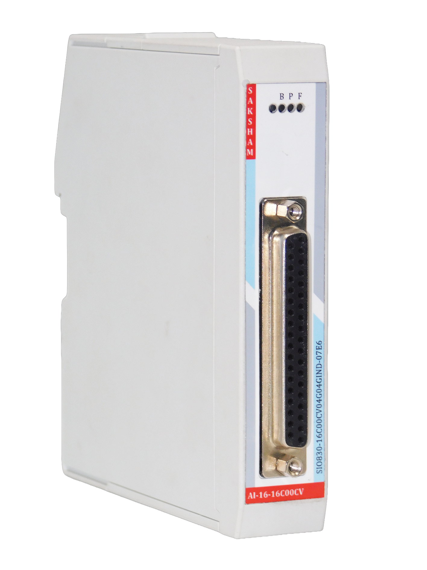
37-Pin D-Sub Female Connector |
| Power Connection |
5 Pin Phoenix Plug-In Screw Connector (De-Coded) |
| Cable Length Max. |
500 m, 1.0 mm² shielded cable |
| Address Space Per Module |
32 Bytes |
16 Bytes |
16 Bytes |
16 Bytes |
16 Bytes |
| Dimension (W x H x D) |
25 x 122 x 115 mm |
— |
25 x 122 x 115 mm |
— |
— |
| Weight |
160g Approx |
| Dimensions (W x H x D) |
— |
25 x 122 x 115 mm |
— |
25 x 122 x 115 mm |
25 x 122 x 115 mm |
| Resolution (with over-range) |
— |
12 Bit |
— |
— |
— |
| Conversion Time Per Channel |
— |
100 ms |
— |
— |
— |
| Diagnostics Alarm |
— |
— |
Yes |
Yes |
Yes |
| Limit Alarm |
— |
— |
Yes |
Yes |
Yes |